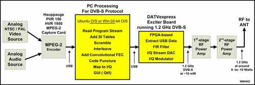
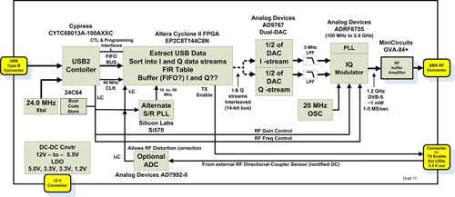
Description: The DATV-Express project was formed to create low-cost solution for Digital-ATV transmission. The open-source project was first announced and described at the TAPR Digital Communications Conference (DCC) in 2011. The design uses a PC to perform most of the DVB processing. The first release of software was run on Ubuntu Linux 32-bit/64-bit. Currently, the software also runs on Windows 32-bit/64-bit.
Description: The DATV-Express project was formed to create low-cost solution for Digital-ATV transmission. The open-source project was first announced and described at the TAPR Digital Communications Conference (DCC) in 2011.
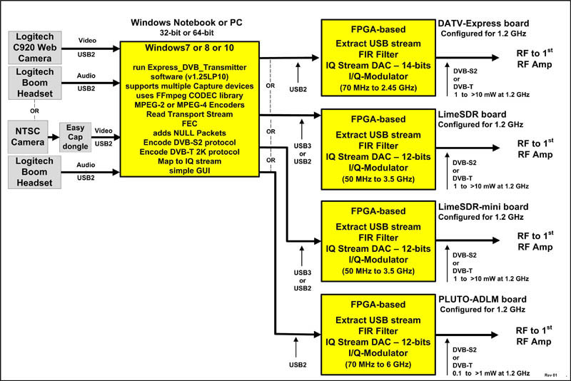
Description: Starting in 2017, the DATV-Express project is now focused on expanding the software to support many low cost DATV SDR boards. The block disgram below illustrates that the current v.1.25LP11 transmitter software for Windows can support any of these four DATV excitor boards:
- DATV-Express Tx board (USB-2)(out of production)
- LimeSDR Tx/Rx board (USB-3 or -2)
- LimeSDR-mini Tx/Rx board (USB-3 or -2)
- PLUTO ADLM Tx/Rx board (USB-2)
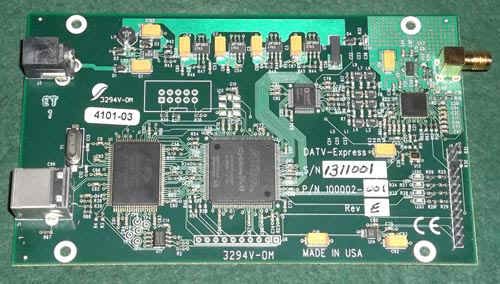
Description: The DATV-Express project was formed to create low-cost solution for Digital-ATV transmission. The open-source project was first announced and described at the TAPR Digital Communications Conference (DCC) in 2011. The photo below is first of the pre-producion board etch layout. Other lower-cost SDR-based Tx/Rx products became available in 2017... and the DATV-Express Project team made the decision in late 2017 to not msnufscture any additional boards when the inventory was depleted.
Description: The DATV-Express project was formed to create low-cost solution for Digital-ATV transmission. The open-source project was first announced and described at the TAPR Digital Communications Conference (DCC) in 2011.
In
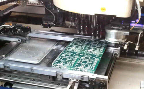
the video link below, four PCBA boards are being assembled by "pick-and-place"
robot placing the SMT components onto the board. The
blank PCBs are arranged as an 2x2
arrays. The robot arm spinning to the right location in order to lower the SMT component
onto the correct footprint...and the board array underneath shifts so that the arm can
reach all four boards.
(The .MP4 video file linked below requires Adobe Media Player [free] or equivalent MP4 player to view. The file is quite large to download – 36 MB Please download this video file if interested (right-click and "save target as") and then view on your local computer)
