Planning a Digital-ATV Station for
DVB-S
W6HHC@ARRL.net
Robbie Robinson – KB6CJZ
KB6CJZ@ARRL.net
Abstract
Most
ham radio Amateur Television (ATV) stations and repeaters in use today still
utilize analog technology. The purpose of this paper is to explain Digital-ATV
(DATV) to other hams, with the hope that it might make the transition from analog-ATV to Digital-ATV a little more straightforward. The paper begins with a review and comparison of various
commercial DTV standards that are in use around the world. A top-down design
methodology session is then conducted to sort through a number of design
alternatives to plan a DATV station. The planning session chooses the DVB-S
standard for DATV over the competing United States-based ATSC standard. The
paper concludes by describing the Forward-Error-Correction factors and
Symbol-Rate factors that determine the RF bandwidth for a DVB-S DATV station.
Key Words
DATV Digital-ATV DVB-
1 - Introduction to DATV
For several years, Robbie and I
have listened to some interesting ham conversations about “...we hams should change analog ATV over to Digital-ATV (aka DATV) to
keep up with technology...”. While the goal seemed simple, the topic was
very complex and not easy to grasp. We found that there really was no simple
place to go...like a “one-stop-shop” for DATV information, especially here in
the United States where ATSC is a standard to be carefully considered. This paper is our attempt to explain
Digital-ATV (DATV) to other hams with the hope that it might make the
transition from analog-ATV to Digital-ATV a little more straightforward.
1.1 - Why
Go Digital ATV?
The main benefits of digital
ATV are:
1) The picture quality can be nearly perfect most of the
time
2) Digital techniques allow error correction from noise,
multi-path
3) Digital techniques allow advanced modulation (less
bandwidth) and compression
4) Digital TV components for hams will become more
common on the marketplace.
5) Analog TV components for hams will start to disappear
from the marketplace.
1.2 - Different Types of Digital Video Broadcasting
Specifications
To
start with, there are three fundamental television broadcasting environments that
are used for commercial Digital Video broadcasting:
- Cable
- Satellite
- Terrestrial
Each of these three different environments requires a different specification as described below.
1.2.1 -
DVB-C (cable)
The
DVB-C standard for cable broadcasting was established by the Digital Video Broadcasting
organization (www.DVB.org). The environment
of cable is very low noise and very low loss.
So resistance-to-noise and lots of error-correction-technology is not
needed for cable digital TV. The nice cable environment allows implementing
higher order modulation schemes starting from QPSK up to 256QAM. Because of the
guaranteed low signal path loss in cable, this does not represent a good choice
of technology for hams to consider.
1.2.2 - DVB-S (satellite)
The
DVB-S standard for satellite broadcasting is designed to work in an environment
that contains lots of signal path attenuation and line-of-sight communication.
To compensate for the weak signals, the DVB-S standard uses different layers of
Forward Error Correction (FEC) for a very robust protection against any kind of
errors. One drawback for hams is that DVB-S was NOT designed to deal with
multi-path environment situations. Typically, the DVB-S uses MPEG-2 for video
data compression and QPSK for modulation and DVB-S can be operated in an RF bandwidth
mode as small as 2 MHz. This is the standard chosen by many European and United
States DATV groups for digitizing ATV.
1.2.3 - DVB-T (terrestrial)
The
DVB-T standard for terrestrial broadcasting by the Digital Video Broadcasting organization
is designed to work in the classic situation where a transmitter is
broadcasting RF signals to home antennas coupled to a digital TV receiver.
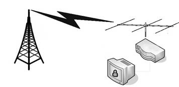
Fig 1 - Terrestrial Reception using a Commercial
Set-Top-Box
In
over-the-air broadcasts, the DTV technology needs to overcome the destructive
effects of multipath reflections. Also, the terrestrial signal path attenuations
can be frequency dependent and can result in a partly distorted received
signal. The negative effects of multipath reflections can be reduced, by using
16QAM modulation for a low effective bitrate per carrier. To reduce the
effective bitrate per carrier, DVB-T spreads out the bitrate over a large
amount of carriers. This spreading out will result in 1,705 closely spaced
carriers (using COFDM...aka Coded Orthogonal Frequency Division Multiplexing)
to create a 6 MHz bandwidth. Creating 1,705 different carrier frequencies with
the conventional approach of VCO's and PLL chips is impossible. If we look at the technology choices for DATV,
then hams will come to the conclusion that DVB-T is the ultimate approach DATV
to use when it comes to robustness. However, the combination of: (1) the high
signal-to-noise ratio which is needed for demodulation, and (2) the big impact
on hardware implementation, let many hams come to the conclusion that the DVB-T
approach is difficult for amateur use.
1.2.4
- ATSC 8-VSB (terrestrial)
What
we have not mentioned, so far, is that the Digital Video Broadcasting
organization standards are only used for commercial TV in Europe, Asia, and the
Pacific...NOT in the
8-VSB
is the 8-level Vestigial Sideband Modulation method adopted for terrestrial
broadcast of the ATSC digital television standard. Like DVB-S, it usually uses MPEG-2 for video
compression and multiple layers of Forward Error Correction (FEC) for a very
robust protection against any kind of errors. Interestingly, the 8-VSB
modulation does not use phase-shift techniques, but uses 8 levels of amplitude
for modulation and demodulation. This modulation approach produces a gross bit
rate of 32 Mbit/s, and a net bit rate of 19.39 Mbit/s of usable data in a 6 MHz
bandwidth. The net bit rate is lower due to the addition of forward error
correction (FEC) codes. While, the set-top ATSC DTV boxes are very common in
1.3 - Drawbacks for DATV
There are two main drawbacks to DATV
for ham radio ATV enthusiasts:
(1) Weak Signal
Reception
Digital TV technology tends to
have “ALL or NOTHING” video performance.
The picture is GREAT thru noise and weakening signals...then POOF, it is
gone. The transition phase between ALL or NOTHING tends to be very narrow.
As Henry AA9XW explained in the Amateur Television of Central Ohio News (ATCO), “Yes, digital [ATV] is ‘noise free’ until
you hit the blue wall. There is 1 dB between perfect and nothing. So don't
expect a lot of DX, since you can't find the signal in the noise without a
spectrum analyzer and BPF [band pass filter].”
(2) High Cost of
Equipment
One advantage of analog ATV was
the cost of equipment, especially transmitting equipment was relatively cheap.
You could buy commercial analog CCTV equipment and easily modify it for ham
radio ATV use. The receiving circuits can be obtained from old home satellite
dishes (DVB-S) that are surplus on e-Bay or internet and can be converted to DATV. But, obtaining transmitters...with image
processing and the modulators...is the main problem. There is no cheap surplus
satellite transmitting equipment around.
Therefore, either you buy boards from European DATV board companies or
you buy the Integrated Circuits used by the transmitters and build your own equipment.
In our opinion, this last approach takes a lot of engineering/software
technical skill that most hams do not possess and requires an investment of a
lot of time. SR-Systems in
1.4 - Status of DATV Today
Groups and clubs of DATV
enthusiasts have shown that digital technology is possible for hams and that
DATV works as expected. Fig 2 is a
block diagram of a basic DVB-S transmitter used by several European groups for
DATV.
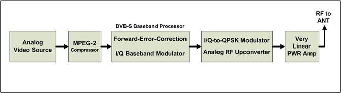
Figure 2 – Block
Diagram of Typical DVB-S Transmitter for Digital-ATV
Figures 3 and 4 are European
examples of what a ham station looks like and the performance that can be
achieved.
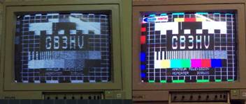
Fig 3 – Comparison of
analog Picture and an DATV
Picture using the same
antennas with weak sigs
(courtesy of G8GTZ, G7LWT & GB3HV)
Fig 4 is a picture of an
early European DVB-S prototype transmitter demonstrated in 2001 at the Friedrichshafen
Ham Fair in Germany by Thomas Sailer-HB9JNX/AE4WA, Stefan Reimann-DG8FAC, et
al.
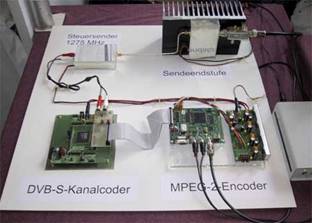
Figure 4 – Prototype
DVB-S DATV transmitter similar to the Block Diagram shown in Fig 2
(courtesy of
Thomas Sailer-HB9JNX/AE4WA, et al.)
In our probing the internet and through having local
conversations, we found that there was a very large burst of DATV efforts by
hams (mainly in European) that lasted from about 2000 to about 2004. Many of
these early ham radio WEB sites on DATV seemed to eventually go dormant:
·
www.D-ATV.com in
·
pagesperso-orange.fr/jf.fourcadier/television/exciter/exciter_e.htm from Jean-François F4DAY went inactive in
2004/2005
·
www.kolumbus.fi/michael.fletcher/dvb.htm Michael Fletcher OH2AUE & OH2FM appears
dormant on DATV since 2003
·
www.G7LWT.com in
From
what we have learned, there are only four or five areas in the
- ATCO has the WR8ATV/R digital DVB-S repeater
output on 1260 MHz
- Nick Sayer, N6QQQ from
- The Lodi
Amateur Radio Club, N6SJV in
- There is a ham from
- There are rumors of a group of hams in either
1.5 - What is the Future for DATV??
Based on what we have learned
while preparing this paper on DATV, we are surprised by the small amount of
current DATV activities in the
Finally, Ken W6HHC personally
finds DATV technology quite complex. Since transmitters for DATV are expensive
or you can design your own...I find the complexity of designing my own DATV
much much more complex than designing my own SSB transmitter or FM transmitter.
In addition, commercial standards continue to evolve. For example: The DVB-S
spec is being replaced by the newer “second generation” DVB-S2 standard. While
DVB-S2 is faster and better (and even more complex - using a new FEC scheme
like Bose-Chaudhuri-Hocquengham), it may threaten to obsolete DATV equipment
built with earlier DVB-S designs?
In bringing this introduction to
DATV to a conclusion, it appears that the mainline ATV-ers in the
2 - Planning a Digital-ATV Station
This section will cover
planning to create our own DATV station.
But to a certain extent (especially in the
·
Some decisions
could be very expensive
·
Some decisions
may lead to an obsolete design
·
Some decisions
could have major technical issues
2.1 - What
Band Should We Plan for DATV?
Robbie
KB6CJZ explains that the view of ham radio bands for ATV and DATV in
- 440
MHz – very crowded - looks like
a difficult band for DATV,
But, RF amps are cheaper
Commercial satellite receivers with up-converters
work fine.
- 920
MHz – presents a tight fit for
DATV,
Also, lots of
noise from “ISM Part 15” devices.
- 1,200
MHz – more room for simplex DATV,
Probably
no room for a DATV repeater-pair.
RF
amplifiers get more expensive.
This
is a clear ham band.
FreeToAir
receivers are plentiful and the IF is in this band with no LNB needed or
conversion.
- 2,400
MHz – probably has room for a
DATV repeater
But, RF amplifiers get even more expensive,
Also, 2.4 GHz region is shared with lots of others
commercial services. Most commercial services are just out of edge of the Ham
band and some “ISM Part 15” devices share the frequencies with the hams.
- 3,400
MHz – RF amplifiers get still
more expensive.
But, probably has room for a DATV repeater-pair.
Standard satellite FreeToAir receivers are plentiful.
LNB’s need no converting.
3.4 GHz is shared only with U.S. Air Force
- 5,800
MHz – RF amplifiers are
expensive.
5.8 GHz region is shared with lots of commercial
services and “ISM Part 15” devices
A narrow band, may not have room for DATV
repeater-pair.
We made the decision to plan to
locate ham home/portable transmitters on the 1.2 GHz band as a good compromise. Later, if we can put up a DATV repeater...the
repeater will output on 2.4 GHz or maybe on 3.4 GHz.
2.2 – Use ATSC or DVB-S Modulation Scheme??
The Introduction section explained
that Europe/Asia/Pacific were using the DVB-S standard for commercial DTV,
using QPSK modulation for video and MPEG-2 compression for audio. But, in the
2.2.1 – First let us Look at DVB-S Transmitters
So
far, we have seen that while there are several ham designs in Europe for DVB-S
D-ATV boards, especially AGAF and SR-Systems, both in
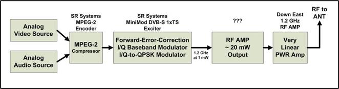
Figure 5 - Block
Diagram of DVB-S Transmitter for DATV
The
MiniMod board and will produce about 1 mWatt RF output. I will need a small RF
amplifier to get that power up to about 25 mWatts to drive the 10 Watt RF. All Digital RF modulations require very
linear Class A power amplifiers. We plan to run a 30W 1.2 GHz linear amp at
about 10 watts or so. Note that the SR-Systems datasheets caution that the RF
output of the MiniMod board is UNFILTERED.
Stefan-DG8FAC has explained to us that this note means that we need to suppress
the second harmonic and the third-harmonic a little. Following the MiniMod output with two 1.2 GHz
amps provides the required harmonic suppression. The DVB-S 1xTS DATV RF signal bandwidth
will be about 2 MHz -to- 3 MHz wide (depending on Symbol-Rate settings
discussed later in Section 3). Table 1
below looks at an estimate of costs for a DVB-S transmitting station.
Table 1 – Cost
Estimate of DVB-S Transmitter
|
Item |
Description |
Manufacturer |
Model |
Cost Estimate Low end |
Cost Estimate High end |
|
1 |
MPEG Encoder Board |
SR-Systems |
MPEG Encoder |
$290 |
$360 |
|
2 |
1.2 GHz FEC & IQ
Modulator for DVB-S |
SR-Systems |
DVB-S 1xTS MiniMOD |
$470 |
$540 |
|
3 |
First RF amp |
?? |
(about
50 mW) |
$25 |
$50 |
|
4 |
RF Power Amplifier 30W (very linear) |
Down East Microwave |
Part Number 2330PA |
$240 |
$240 |
|
|
TOTAL |
|
|
$1,025 |
$1,190 |
2.2.2 – Next let us Look at ATSC Transmitters
While there are several ham
designs in
The ATSC transmitter block
diagram shown in Fig 6 looks almost
the same as the DVB-S block diagram that was shown back in Fig 5.
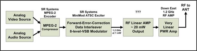
Figure 6 - Block
Diagram of ATSC Transmitter for DATV
The MiniMod ATSC board will also
produce about 1 mWatt of RF output. I will need a small RF amplifier to get
that power up to about 25 mWatts to drive the final 10 Watt RF amplifier. All Digital RF modulations require very
linear Class A power amplifiers. We plan to run a 30W 1.2 GHz amp at about 10
watts or so. Note again that the SR-Systems datasheets caution that the RF
output of the MiniMod board is UNFILTERED.
What this means is that we need to suppress the second harmonic and the
third-harmonic a little. Following the
MiniMod output with two 1.2 GHz amps provides the required harmonic
suppression. The 8VSB signal will be about 5.5 MHz wide. Table 2 looks at an estimate of costs for an ATSC transmitting
station.
Table 2 – Cost
Estimate of ATSC Transmitter
|
Item |
Description |
Manufacturer |
Model |
Cost Estimate Low end |
Cost Estimate High end |
|
1 |
MPEG Encoder Board |
SR-Systems |
MPEG Encoder |
$290 |
$360 |
|
2 |
1.2 GHz FEC & IQ Modulator
for ATSC |
SR-Systems |
ATSC MiniMOD |
$852 |
$925 |
|
3 |
First RF amp |
?? |
(about 50 mW) |
$25 |
$50 |
|
4 |
RF Power Amplifier 30W (very linear) |
Down East Microwave |
Part Number 2330PA |
$240 |
$240 |
|
|
TOTAL |
|
|
$1,407 |
$1,675 |
2.3 – Comparing Possible DATV Receiving Stations
Now we will look at possible choices for the DATV
receiving station. The video can be displayed on an old analog TV, a new DTV,
or a desk-top computer or a notebook computer. In Fig 7, we show nine possible alternative configurations for DATV
receivers: four configurations are aimed at receiving ATSC ham signals and five
configurations are aimed at receiving DVB-S ham signals.

Figure 7 - Possible DATV Receiver Choices
Now we will walk through each of the receiving
station alternatives that are shown in Fig
7 ...starting with receiving ATSC ham signals.
Alternative 1 – Using a Terrestrial ATSC STB
The first approach for receiving
ATSC is to use the cheap ($50 new) ATSC terrestrial SetTopBoxes that have been
made common by the
Alternative 2 – Using Cable-Ready DTV
In the second approach, some
models of “cable-ready” digital TVs can receive QAM (for cable) as well as ATSC
(for terrestrial) and will correctly handle the MPEG-2 audio OK. Nick-N6QQQ in
Alternative
3 – Using a Computer PCI ATSC Tuner
In the next approach, we use a
PCI board designed to add an ATSC TV tuner to a PC computer. Nick-N6QQQ has
reported MiniMod ATSC success with using computer peripheral tuners, simply
because all they do is take the 8VSB and put out the MPEG-2 transport stream.
The computer winds up doing the rest of the work by decoding the MPEG-2 video
and the MPEG-2 audio. The Hauppauge WinTV-HVR-1600 PCI TV Tuner Card – 1101
covers analog (NTSC) and DTV (ATSC) for under $100. Another interesting
approach for a PC computer is the Silicon Dust HD HomeRun box that networks to
the computer. Again, we need a down-converter to take the incoming 1.2 GHz
signal and bring it down to the range of U.S. ATSC DTV tuners.
Alternative
4 – USB ATSC Tuner for Notebook
In this approach, we use an ATSC
tuner with a USB output that can deliver to a Notebook computer (no room for
PCI card). The notebook will again accept the MPEG-2 transport stream output
and provide for the presenting the video
and audio. The Hauppauge WinTV-HVR-950Q TV Tuner Stick can be purchased on the
internet for around $70 new. Again, we need a down-converter to take the
incoming 1.2 GHz signal and bring it down to the range of U.S. ATSC DTV tuners.
Alternative
5 – Using a Satellite DVB-S STB
Our first approach to receiving
DVB-S transmissions uses a DVB-S satellite box (commonly called Free-To-Air or
FTA). A “composite RF” output from the STB can go straight into an old analog
TV set. The frequency range of the DVB-S STB tuner range for satellites will
include the 1.2 GHz ham band, so no down-converter is needed. The ViewSat
VS2000 Xtreme is an example of a DVB-S FTA STB that can be purchased new for
about $100 or even less for a used unit on e-Bay.
Alternative 6 – Using DVB-S STB with DTV
This approach is the same as the
DVB-S alternative #5 above, except it takes the S-Video output of the
Free-to-Air DVB-S SetTopBox to provide the input to a HDV set.
Alternative 7 – Computer PCI DVB-S Tuner
In this approach, a PCI DVB-S
tuner board is installed in the PC computer. The Hauppauge WinTV Nova-s PLUS DVB-S
PCI Card costs less than $100.
Alternative 8 – USB DVB-S Tuner for Notebook
This approach uses a DVB-S USB
tuner box (for example: the SkyStar USB2 model costs about $100) to output
directly to the USB port on the notebook computer.
Alternative 9 – Using DVB-S STB with Notebook
This approach is very similar to
#6 above except we add an S-Video to USB converter to take the STB output to
the USB input on the notebook computer. A typical S-Video-to-USB converter is
the Startech.com USB 2.0 and costs about $50
through Radio Shack (in addition to the STB cost) and other stores on the
internet.
2.4 - Selecting Our DATV Station
Robbie and I had both hoped for
an ATSC approach for DATV because of the easy availability of low-cost
terrestrial STBs in the
Now that we have chosen our DATV
transmitting station, any of the DATV receiving station approaches ALTERNATIVE
#5 through ALTERNATIVE #9 in Fig 7
will work well. The costs of each of these five receiving approaches are
reasonable. So the reader can choose the approach that appeals to him. Ken-W6HHC
will choose ALTERNATIVE #8 because he wants to use his notebook computer (instead
of a TV set) for his home DATV station. Robbie-KB6CZJ prefers to go with
ALTERNATIVE #5, because he prefers the wide-availability and the feature-rich-capability
of a DVB-S FTA SetTopBox.
There are still a few details to
sort out for our station, but hopefully you can see that this top-down approach
to planning a DATV station provides a “big picture” of alternatives...allows us
to understand the trade-offs....and allows a direction to be chosen.
3 - Understanding Symbol-Rates, FEC and RF Bandwidth for DVB-S
Ken W6HHC does not feel
comfortable unless he understand the basic concepts he is working with. The
promise of DATV to deliver video in “less bandwidth than analog ATV” is a great
goal, but lets study the factors affecting RF bandwidth for DVB-S so that the
factors are fully understood.
Using the DVB-S standard to
transmit a digital ATV signal involves:
• QPSK
(Quadrature Phase Shift Keying) modulation
• FEC
(Forward Error Correction) algorithms
• MPEG-2
compression data rates for video
• Video
bit-rate needed
• Net Data
Bit-Rate available
• Symbol-Rates
• RF
Bandwidth
This section will now walk
through these various DATV factors and arrive at determining the resulting RF
bandwidth.
3.1 - Video Data-Rate and Compression
Fig 8 shows the basic flow of
video stream and data rates through a DVB-S transmitting block diagram. For
DATV, the analog camera output is first digitized by the MPEG-2 Encoder board that
is shown in Fig 8, and then the
video stream is compressed by the MPEG-2 algorithm.
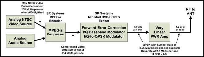
Figure 8 – DATV Block
Diagram Showing Various Data-Rates and Symbol-Rates for DVB-S QPSK
(for 2.25
Msymbols-per-sec, the Bandwidth is 3 MHz)
The information in Table 3 comes mainly from the excellent
paper written by Dr Gorry Fairhurst in 2000, called “MPEG-2 Overview”. [Note: you can find a link to this paper in
Wikipedia.] This table allows you to compare the video data stream rates with
and without MPEG-2 compression. The reason the compressed video data rate
varies in Table 3 is that the amount
of motion in the picture affects the value. The low compressed value means
little motion in the video scene and the higher value means a lot of motion.
Table 3 – Camera Video Data Streams
and MPEG-2 Data Streams
|
Video Data Stream |
Data-Rate |
Notes |
|
Analog NTSC camera |
168 Mbits/sec |
A/D
digitized, uncompressed |
|
NTSC MPEG-2 |
2-3 Mbits/sec |
compressed |
|
VHS MPEG-2 |
1-2 Mbits/sec |
compressed |
|
|
|
|
|
Analog PAL camera |
216 Mbits/sec |
A/D
digitized, uncompressed |
|
PAL MPEG-2 |
2.5-6 Mbits/sec |
compressed |
|
|
|
|
|
HDTV camera |
1-1.5 Gbits/sec |
uncompressed |
|
HDTV MPEG-2 |
12-20 Mbits/sec |
compressed |
Notice in Table 3 that the uncompressed NTSC camera video stream is 168
Mbits/sec, while the uncompressed PAL camera video stream is 216
Mbits/sec. The NTSC video stream
data-rate is a 22% reduction from PAL data-rate.
Stefan-DG8FAC of SR-Systems
(located in
3.2 - FEC Inflation of Video Stream Data-Rate
Forward Error Correction (FEC) is
a technology that not only can detect an error on the received signal, but adds
enough redundancy of the data so that it can correct the wrong bit. It can correct two wrong bits. Since redundancy increases the data-rate of
the video stream, there is a trade-off between more redundancy and the required
video data-rate becoming too large. As we will see a little later in this
article, the larger the video stream data-rate, the higher the required RF
bandwidth. So at some point the FEC algorithm will not have enough redundancy
to correct too many errors. Then, if not all the errors are corrected the DATV
screen will eventually go blank.
The DVB-S commercial television
standard uses two different Forward-Error-Correction (FEC) algorithms together
in order to provide protection against noise errors and multi-path errors. The
first FEC algorithm is called Viterbi.
The second FEC algorithm is called Reed-Solomon.
The Viterbi FEC algorithm can be
configured for different levels of error correction. Theses different Viterbi
configuration/redundancy settings are usually called: 1/2, 2/3, 3/4, 5/6 and 7/8. The first number (“1” in the case of
configuration “1/2”) is the number
of input bits into the algorithm. The second number (“2” in the case of
configuration “1/2”) is the number
of output bits from the FECviterbi algorithm. So the MPEG-2 output data stream
is “inflated” 100% by this FEC algorithm configured for 1/2. That is...for
every bit going into the FEC engine, two bits come out. A FECviterbi algorithm configured for 3/4, for example, would
inflate the MPEG-2 output data stream by 33%. So FEC levels can really inflate
the data-bit-rate going to the RF modulator; the MPEG-2 algorithm compresses
the video stream, but the FEC algorithms start to expand the required
data-bit-rates again.
The Reed-Solomon FEC algorithm
has a fixed configuration setting. Its
data stream “inflation rate” is 188/204. So for every 188 bits going into the
FECreed-solomon algorithm, 204 bits will
come out...an additional FEC inflation of 8.5%.
3.3 - Digital Modulation Symbols and Symbol-Rates
Digital modulation technology
like BPSK (for example PSK-31), QPSK (Quad Phase Shift Keying for example like
DVB-S) and QAM256 (Quadrature Amplitude Modulation with 256 “constellation
points”) have the ability to put more information into a narrow frequency
spectrum than analog modulation. The complexity of the digital modulation
scheme, allows us to pack more “data bits” into each SYMBOL. Table
4 lists out the details on how many data bits can be packed into a symbol
for several well know digital modulation technologies.
Table 4 – Symbol Bit-Packing for
Various Digital Modulation Technologies
|
Modulation Scheme |
Data Bits per Symbol (Me) |
|
BPSK |
1 |
|
QPSK |
2 |
|
8-VSB |
3 |
|
QAM16 |
4 |
|
QAM256 |
8 |
This table means that QPSK will
pack two data bits into each symbol being modulated. If we know the final
output data-bit-rate (I will call this inflated data rate the “Gross
Data-Bit-Rate”) we need for the television signal, then the “symbol-rate” we
need is exactly one-half of that data-bit-rate.
For example:
Gross
Data-Bit-Rate = 4.5 Mbits/sec
Symbol-Rate
Needed = 2.25 Msymbols/sec
The formula to calculate the
Symbol-Rate setting that we need for our DVB-S transmitter is:
Symbol-Rate
Needed = ![]()
Where:
NDBR = Net Data Bit Rate (aka the information rate)
Same as MPEG-2 output data rate listed in Table 3
Me = Modulation
Efficiency (value is 2 for QPSK is listed in Table 4)
CRv = Correction Rate setting for Viterbi algorithm
(1/2, 3/4, etc)
CRrs = Correction Rate value for Reed-Solomon algorithm is 188/204
We will now calculate an example
for QPSK where the output of MPEG-2 is 2.4 Mbits/sec and FECviterbi is configured
to 1/2.
Symbol-Rate
Needed = ![]()
![]()
Symbol-Rate
Needed = ![]()
Symbol-Rate
Needed = 2.60
Msymbol/sec
If we change the FECviterbi setting to
3/4, then the CRv value becomes 3/4 and the results are:
Symbol-Rate
Needed = 1.73 Msymbol/sec
The Symbol-Rate that is needed
was reduced because the “inflated data-rate” caused by a lot of FEC redundancy
was reduced. If you look at Table 5,
it shows the Net Data Bit Rate that can be supported by a particular
Symbol-Rate using several FEC settings. The FEC setting needs to result in a
number of Net Data Bit Rate that is at least 2.4 Mbits/sec. The red values in
the table show FEC settings or Symbol-Rates that result in a Net Data Rate of
less than 2.4 Mbits/sec that we set as our goal for MPEG-2 video stream output.
Table 5 – Net Data Bit-Rates for
DVB-S at a given RF Bandwidth
3.4 - RF Bandwidth for DVB-S DATV
It turns out, one of the
advantages of digital-ATV is it can be more bandwidth-efficient than analog
ATV. With QSPK modulation you actually
have the ability to easily make the DATV RF bandwidth as narrow as 2 MHz or 3
MHz without giving up any noticeable quality. This is because the commercial
DTV standards planned to transmit several Television streams inside one normal
(old) RF TV bandwidth.
The final formula is for DATV
Bandwidth (BW). For QPSK modulation, the formula for RF BW is:
RF BW =
1.33 x Symbol-Rate
This Bandwidth is the spacing
that can be used for placing adjacent DATV station center-frequencies. This
value of Bandwidth is where the signal is down about -15 dB or more. The
expression "occupied bandwidth" is sometimes used to refer to a
bandwidth that is 1.19 times the symbol rate, where the signal is down by
approximately -10 dB.
If the Symbol-Rate used is 2.25
Msymbols-per-sec for example, then:
RF BW =
1.33 x 2.25 Msymbols/sec = 3.0 MHz
If we can use a Symbol-Rate of
only 1.5 Msymbols/sec, then the bandwidth reduces to:
RF BW =
1.33 x 1.5 Msymbols/sec = 2.0 MHz
Again, Table 5 on the preceding page provides an overview of what RF
Bandwidth you can choose and what the resulting Net Data Bit Rate can be
supported will be for various FEC selections.
4 – Conclusion and Our Future Plans
In reviewing the results in Table 5, we have concluded that we will
use an RF Bandwidth of 2.5 MHz to support an NTSC MPEG-2 output of 2.4
Mbits/sec by selecting FEC to be 3/4. We plan to put together a DATV station
soon. When we do test the station, we
will measure the NTSC MPEG-2 video stream that is really required. If our suspicions that we will see a NTSC MPEG-2
video stream at around 2Mbits/sec are confirmed, then we probably change to a 3
MHZ RF BW by using the FEC setting of 1/2. This FEC setting will produce high
DATV signal correction capability in one-half of the normal 6 MHz analog ATV
bandwidth.
This paper has tried to explain many
DATV concepts in order to provide understanding to hams about what is involved,
without diving into the intense mathematics that is so common in Digital
Communications text books. The internet is a wonderful resource. The internet and Google and Bing make
research so much easier and faster than paging through magazines and books.
Probably 95% of the material in this paper would never have been known to us in
Our plans are to first order a
first set of DVB-S boards from SR-Systems and do some testing and some
measurements. We have plans to do some field tests to determine the picture
quality sent to an Emergency Operations Center (EOC) from portable locations in
the hills of
Referenced Links and Related
Links
Advanced Television Systems Committee (ATSC) www.ATSC.org
Digital Video Broadcasting organization (DVB)
www.DVB.org
Amateur Television of Central Ohio www.ATCO.TV
British ATV Club - Digital Forum www.BATC.org.UK/forum/
CQ-TV magazine from BATC (mostly analog) www.BATC.org.uk/cq-tv/
Darren Storer-G7LWT on “DATV / Digital Amateur
Television Primer” www.G7LWT.com/datv.html
Thomas Sailer-HB9JNX/AE4WA, et al on “Digital Amateur
TeleVision (D-ATV)”
www.baycom.org/~tom/ham/dcc2001/datv.pdf
DXzone Digital-ATV Links www.dxzone.com/catalog/Operating_Modes/Digital_ATV/
Noel Matthews-G8GTZ on “The GB3HV digital project – part 1” http://www.g7lwt.com/documents/datv/GB3HV%20digital%20article1.pdf
OCARC newsletter DATV Introduction article on “ATV – the Digital Fork in the Road” www.W6ZE.org/DATV/TechTalk74-DATV.pdf
OCARC newsletter DATV article “Planning a Digital-ATV
Station” www.W6ZE.org/DATV/TechTalk75-DATV.pdf
OCARC newsletter article “Understanding Symbol-rates,
FEC, and RF Bandwidth for DVB-S” www.W6ZE.org/DATV/TechTalk76-DATV.pdf
Jean-François Fourcadier-F4DAY on “The POOR MAN's
DIGITAL ATV TRANSMITTER” pagesperso-orange.fr/jf.fourcadier/television/exciter/exciter_e.htm
Rob Swinbank-MØDTS on details of “Poor Man's Digital
ATV Transmitter – LIVE update” www.M0DTS.co.uk/datv.htm
Nick Sayer-N6QQQ blog on “Putting together an ATSC
DATV station” http://nsayer.blogspot.com/search/label/ham
South West Herts UHF Group in
PE1JOK and PE1OBW on “The Ultimate Resource for
Digital Amateur Television” www.D-ATV.com
David Sparano on “WHAT EXACTLY IS 8-VSB ANYWAY?” www.broadcast.net/~sbe1/8vsb/8vsb.htm
AGAF D-ATV components (Boards) www.datv-agaf.de and www.AGAF.de
SR-Systems D-ATV components (Boards) www.SR-systems.de
Typical Internet store for FTA DVB-S SetTopBox Receivers
www.GoSatellite.com